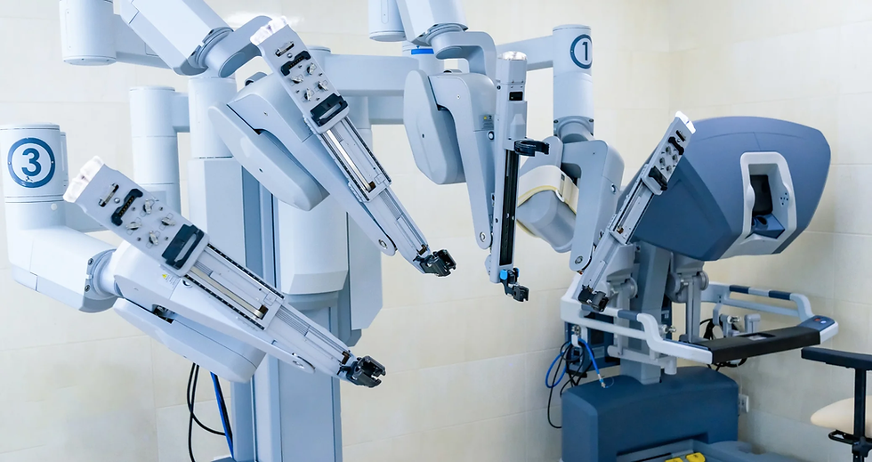
Linear Actuators for Medical Equipment: Requirements and Standards
- ele
- Apr 29
- 9 min read
A linear actuator used in medical equipment generally must support medical electrical safety (commonly aligned with IEC 60601-1), EMC compliance (commonly aligned with IEC 60601-1-2), and disciplined risk management and quality processes (commonly ISO 14971 and ISO 13485). Beyond standards “names,” the actuator must be engineered and documented so your integrated medical system can demonstrate basic safety and essential performance, safe behavior under fault conditions, and suitability for the device’s hygiene/environment (cleaning/disinfection, IP rating needs, corrosion/washdown tolerance). The most successful teams translate standards into a requirements + evidence chain—not a one-time checkbox.

Key Takeaways (Quick Answer)
The system is certified for medical use; the actuator must provide component evidence that enables system compliance.
For electrical and EMC topics, focus on IEC 60601-1 and IEC 60601-1-2 implications: leakage current, insulation/clearances, and emissions/immunity.
For compliance execution, build your documentation and testing around ISO 14971 risk management and ISO 13485 design controls.
For safety behavior, define what happens during faults (safe stop, limit protection, overload/thermal behavior) and map it to the appropriate functional safety approach (often involving ISO 13849-1 depending on the hazard/risk assessment).
For hospital reality, don’t skip cleanability, disinfection compatibility, IP rating requirements, and corrosion/washdown resistance.
The real question: what standards apply to the actuator vs the medical system?
In most medical device programs, regulatory reviewers care most about the complete medical electrical system and its intended use. A linear actuator is a subsystem—often a major contributor to motion hazards, electrical noise paths, and failure modes. That’s why many teams ask, “Do I need IEC 60601-1 for the actuator itself?”
A practical way to think about it:
Standards guide what your system must prove (patient safety, essential performance, EMC).
The actuator must provide design features and documentation that make those system-level proofs achievable.
Why “component compliance” is necessary but not sufficient
Even if an actuator supplier provides a certificate or test report, you still need:
evidence that the actuator is integrated correctly,
confirmation that system configurations preserve safety/EMC margins,
a risk assessment showing your design controls and mitigation measures are adequate.
So treat “actuator standards” as a supply enablement step, not the end of your compliance journey.
Electrical safety requirements (IEC 60601-1 and the actuator’s role)
Basic safety and essential performance, patient safety, and risk linkage
Medical electrical safety requirements aim to prevent unacceptable risk from electrical hazards and ensure performance is maintained where required. In actuator-driven devices, the actuator influences:
conductive and capacitive coupling paths,
grounding/earthing effectiveness,
insulation integrity,
failure conditions (e.g., unexpected motion, stuck motion, or unsafe energy delivery).
Your engineering job is to ensure the actuator design and its electrical integration support the system’s obligations.
Leakage current implications for actuators (what to control)
Leakage current can be affected by:
motor and drive circuitry topology,
cable routing and shielding,
connector quality and insulation performance,
filters and how they’re referenced to protective earth,
the design of housings and barriers separating patient-accessible parts from energized parts.
Actionable approach: in your risk analysis, explicitly consider leakage paths relevant to your device type (patient-contact vs non-patient-contact, grounded vs floating arrangements, environment like wet cleaning). Then require the actuator supplier to provide the evidence you need (test documentation and integration guidance). If you lack supplier detail, you must close gaps with system-level testing.
Insulation, dielectric strength, and protective earthing/bonding
Actuators include windings, insulation layers, motor housings, cable assemblies, and mechanical interfaces. Key concerns typically include:
insulation resistance and aging robustness (especially under cleaning chemicals and thermal cycling),
dielectric withstand behavior,
creepage and clearance considerations (particularly where insulation barriers and printed barriers meet),
the effectiveness of protective earth bonding for accessible metal parts.
Because these are safety-critical topics, the best practice is to:
request insulation-related test reports from the supplier,
specify connectorization and protective bonding requirements in your design spec,
plan system dielectric/earth tests as part of verification.

EMC requirements for medical devices (IEC 60601-1-2)
Medical EMC compliance matters because actuators can generate and couple electromagnetic energy through:
motor commutation and drive switching,
cable harnesses acting as antennas,
feedback/control lines picking up noise,
grounding and shielding interactions.
What typically makes actuators EMC-sensitive
Actuator systems often include both “power” and “control” paths. EMC risk increases when:
cables are routed in ways that increase coupling,
shielding is absent or improperly terminated,
connectors or harnesses differ from supplier-tested configurations,
the control system has inadequate filtering or separation between noisy and sensitive circuits.
Evidence you’ll need for EMC (and what OEMs should plan)
EMC is usually validated at the medical system level, but your actuator procurement should still demand:
supplier EMC characterization and test method summaries,
documentation of shielding/termination practices,
guidance on allowable cable lengths, routing, and connector mating options,
change-control expectations (because EMC can change with seemingly small build variations).
If supplier documentation is limited, plan system-level EMC testing early to avoid late surprises.
Risk management and quality system expectations
Standards titles can look abstract, so here’s how they translate into engineering work you can execute.
ISO 14971 for medical actuators: risk analysis you must perform
ISO 14971 expects a structured approach to:
identifying hazards (electrical shock, unexpected motion, entrapment, overheating, degraded performance, cleaning-induced failure),
estimating and evaluating risks,
implementing risk controls,
verifying controls and tracking residual risk.
For linear actuators, hazards often include:
fault motion (unexpected start/stop, runaway motion),
end-of-travel failure (overtravel against stops),
overload/overheating causing unsafe behavior,
sensor failure (position feedback loss, limit switch failure),
degradation over time (wear, backlash growth, contamination effects),
cleaning/disinfection effects on electrical insulation and mechanical integrity.
Your risk file should explicitly connect:
risk to controls,
controls to requirements,
requirements to verification evidence.
ISO 13485 and traceability: how you prove design control
ISO 13485 is about your quality management system and design control discipline. Practically, it means you need:
traceability from user needs → system requirements → actuator requirements,
documented reviews and design decision records,
controlled changes (especially to cables, connectors, and control logic),
records of supplier qualification and incoming verification.
Even if you buy “ready” actuator modules, medical device expectations usually require evidence that you managed integration risk and changes under controlled conditions.
Verification vs validation (V&V): the proof chain
A reliable V&V plan separates:
Verification: “Did we build what we said we would build?”
test the actuator/system against stated requirements.
Validation: “Does the system meet intended use in the real context?”
test against realistic conditions, including normal use and foreseeable misuse.
For actuators, validation often includes:
endurance under duty cycles,
cleaning/disinfection cycles,
fault scenario demonstrations (within safe test procedures),
performance under worst-case load distributions.
Functional safety and failure handling (safe stop, overload, fault detection)
Linear actuators introduce motion and energy transfer. That’s why safety engineering can’t stop at “it runs.” You must define behavior under fault conditions.
ISO 13849-1 safety—when it becomes relevant
ISO 13849-1 may become applicable when you implement safety-related control functions (for example, ensuring a safe stop on hazardous faults). Whether it’s the right framework depends on your risk assessment and the safety function design.
Rather than claiming universal applicability, the correct approach is:
use ISO 14971 to determine hazards and required safety integrity,
select the appropriate safety standard(s) for those safety functions,
then implement, validate, and document the design.
Designing for fault conditions (sensors, limits, brakes, control logic)
Common actuator-related safety controls include:
End-of-travel protection
mechanical stops plus electronic limits (design depends on architecture)
Overload protection
current limiting, torque limiting, or mechanical slip/fail-safe design
Thermal protection
motor/drive thermal behavior and controlled shutdown
Fault detection
feedback plausibility checks (position sensors), watchdogs, communication loss behavior
Safe stop behavior
define whether the system should stop immediately, hold position, release motion safely, or enter a fault state
A high-quality specification makes these behaviors measurable:
what qualifies as a fault,
how quickly the system transitions to safe state,
what the user sees/hears/experiences (alarm, indicators),
what happens on restart (lockout rules).
Also ensure mechanical design supports the electrical logic. For example, a software limit without a dependable physical protection strategy may not be enough for foreseeable misuse.
Mechanical, hygienic, and environmental requirements
Medical equipment lives in real rooms: cleaning schedules, disinfectants, moisture exposure, and daily mechanical wear.
Limit protection, pinch/entrapment mitigation, and end-of-travel safety
Linear actuators can create pinch points depending on geometry. Your design controls should consider:
mechanical guarding and spacing,
safe overtravel behavior,
reliable end-of-travel detection (and what happens if sensing fails).
These hazards belong in the risk file alongside electrical and EMC hazards.
Cleaning and disinfection compatibility
“Compatible with cleaning” isn’t a marketing phrase—it must be engineered. For actuators and their cable/harnessing:
verify that cleaning agents don’t degrade insulation,
ensure seals and cable glands maintain integrity,
confirm that disinfection processes don’t swell plastics, corrode metals, or compromise connectors.
In practice, you should specify:
the chemicals and exposure conditions used by the end user (or representative test chemicals),
the number of cycles and timing,
acceptance criteria for electrical and mechanical performance after cleaning.
IP rating requirements, corrosion resistance, and washdown resistance
An IP rating is a useful shorthand, but it must match your actual use case. For example:
Some devices tolerate splash cleaning.
Others require more aggressive washdown protocols.
Your requirements should address:
ingress protection appropriate to cleaning intensity,
corrosion resistance under typical hospital environmental exposure,
mechanical durability under thermal cycling and repeated motion.
If the actuator supplier offers IP ratings, you still need to confirm that:
seals remain intact over lifecycle and after cable handling,
connectors and harness entry points are included in the protection assumptions.
Materials biocompatibility (when the design touches patients)
If parts are patient-contacting or accessible, materials selection can become a compliance and safety topic. In those cases, you may need documentation supporting material safety and suitability.

How to specify a medical linear actuator (requirements doc checklist)
If you want fewer surprises later, write your actuator requirements like an engineering spec, not a sales wishlist. A strong document typically includes:
Performance specs
required force/torque capability (including duty cycle and duty peaks)
required stroke length and speed profile (including acceleration/jerk limits if relevant)
acceptable position accuracy and repeatability
backlash/backdrive behavior (important for holding and comfort)
noise/vibration constraints where the device environment demands it
Safety specs
defined safe stop behavior for faults
required end-of-travel protection strategy (sensing and mechanical support)
overload/thermal protection behavior and recovery/lockout rules
fault detection coverage (e.g., feedback missing, limit reached, motor stalled)
Interface specs
feedback type (encoder, potentiometer, hall sensors—whatever your system needs)
control interface requirements and allowable wiring practices
connectorization requirements (keyed designs, supported mating, shielding termination expectations)
cable management guidance to preserve EMC and safety margins
Documentation specs (what you ask the supplier for)
electrical safety-related test reports (as applicable)
EMC test summaries and integration boundaries
reliability/endurance test summaries where available
material documentation and maintenance/cleaning compatibility evidence
change control and traceability commitments (critical for regulated programs)
Validation plan template (what to test before release)
Validation should reflect both normal operation and foreseeable faults/maintenance.
Verification testing list (against requirements)
functional movement tests across load range and stroke
end-of-travel behavior and limit protection tests
overload and thermal protection behavior tests
electrical continuity/insulation-related checks (as required by your validation plan)
EMC pre-checks in representative configurations
cleaning/disinfection mechanical and electrical performance checks (representative cycle counts)
Validation testing list (system-level, intended use)
endurance under realistic duty cycles
performance after cleaning cycles in worst-case conditions
fault scenario tests within safe, controlled procedures (and operator/IEC-safe handling)
usability checks tied to essential performance (comfort, smoothness, stability)
Your exact test matrix depends on device classification and regulatory pathway, but this structure keeps you aligned with the core logic of IEC/ISO frameworks: risk → requirements → verification/validation evidence.
Common selection mistakes (and how to avoid them)
Choosing only by force and stroke
Medical actuators must also satisfy safety behavior, electrical integration, and environmental robustness.
Treating IEC/EMC as “documentation only”
If integration changes (cables, shielding, harness layout), EMC and leakage behavior can change.
Under-specifying fault behavior
“The controller has limits” is not enough. You must define how the system responds to sensor failures and overload/stall conditions.
Skipping cleaning impact validation
Disinfectants and moisture can degrade insulation or seals. Cleaning compatibility must be engineered and tested.
Assuming ISO 14971 is only paperwork
A real risk file drives concrete requirements: what you build, what you test, what you accept.
Conclusion: build compliance from risk to evidence
The most reliable path for medical linear actuators is not “find a standard and hope it works.” Instead:
interpret relevant standards as system obligations (electrical safety, EMC, performance),
run ISO 14971 risk management to identify actuator-related hazards,
translate risks into measurable actuator and system requirements,
execute verification and validation to generate evidence, and
enforce design control and traceability under ISO 13485.
That is how you move from “an actuator that can move” to “a motion subsystem that supports patient safety and dependable clinical operation.”
FAQ
1) Do I need an “IEC 60601-1 certified” linear actuator?
Usually, what matters most is whether your medical system meets IEC 60601-1 obligations. Actuators can provide helpful supplier evidence, but certification is generally system-level. Your best practice is to request relevant supplier test documentation and verify compliance through your integration + system testing.
2) What does “leakage current requirements” mean for actuator design?
It refers to acceptable electrical leakage behavior and electrical safety constraints that depend on your device architecture (grounding, enclosure, cabling, insulation, environment). The actuator and its integration must be designed so leakage-related hazards are mitigated and validated under your medical use conditions.
3) How do I ensure EMC compliance for motorized medical equipment?
Plan for EMC early by controlling actuator drive characteristics, shielding, cable routing, grounding/earthing strategy, and connectorization. Then validate EMC at the medical system level in representative operating states.
4) When does ISO 13849-1 apply to medical linear actuators?
It becomes relevant if you implement safety-related control functions (as determined by your risk assessment). ISO 14971 drives which hazards need safety functions and what level of safety integrity is required; then you choose the safety approach accordingly.
5) What IP rating do I need for a medical linear actuator?
There isn’t one universal IP rating. IP requirements must match the device’s cleaning/disinfection method, exposure to moisture, and intended environment. Specify the expected cleaning agents and exposure, then validate.
6) Can I use an industrial linear actuator in a medical device?
Sometimes, but it’s not plug-and-play. You must perform risk assessment, ensure electrical safety and EMC suitability, confirm cleaning compatibility and long-term reliability, and validate the integrated medical system.


Comments