How to Wire a 4 Buttons DC Motor Controller for Actuators
- Xie
- Jan 29
- 13 min read
What is a 4 Buttons DC Motor Controller?
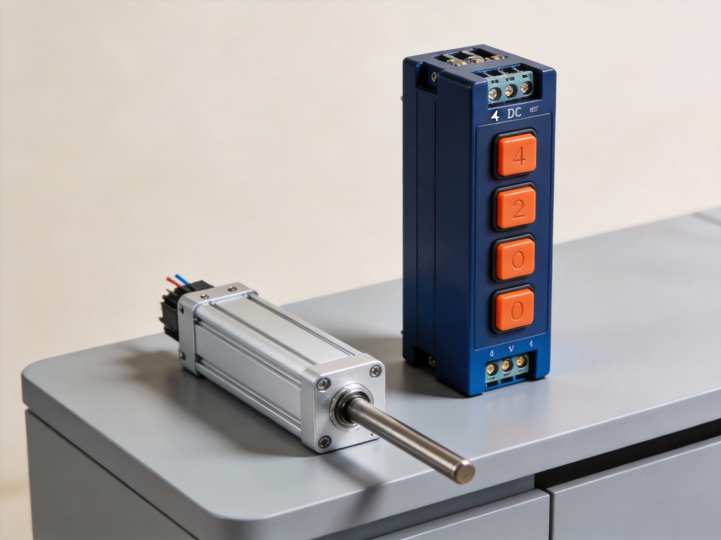
A 4 Buttons DC Motor Controller is a compact, user-operated device designed to command the motion of a linear actuator or DC motor. It provides a simple interface for manual control, typically offering forward, reverse, stop, and sometimes variable speed functions. For precise actuator positioning in applications like medical beds or industrial lifts, selecting a reliable controller is critical. MEIMOVE engineers prioritize controllers with clear tactile feedback and robust signal output to ensure operational reliability.

1. Core Function and Interface
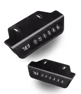
1.1 Defining the Four-Button Interface
The core of this controller is its four-button layout, each mapped to a specific motor command. The standard configuration includes two directional buttons (e.g., "Up"/"Extend" and "Down"/"Retract"), a "Stop" button for immediate halting, and a "Speed" button for cycling through preset velocity levels. This design provides intuitive, single-handed operation, a key advantage in ergonomic applications.
In practice, the stop function is crucial for safety, often designed as a momentary switch that cuts power instantly when pressed, unlike the latching action of the directional buttons.
1.2 Primary Role in Actuator Systems
This controller acts as the command center between the user and the motor's drive electronics. It sends low-voltage control signals (often 12V or 24V DC) to a separate motor driver or integrated control box, which then regulates high current to the actuator. Its primary function is translating simple user input into precise motion control sequences.
Field experience shows that a quality controller must handle signal bounce and provide clean, debounced output to prevent motor stuttering or unintended movements, a common point of failure in cheaper units.
2. Internal Components and Operation
2.1 Key Internal Components
Internally, a typical 4-button controller contains a printed circuit board (PCB) with a microcontroller or logic chip, tactile switches, status LEDs, and output connectors. The microcontroller interprets button presses and generates the corresponding pulse-width modulation (PWM) or logic-level signals. For example, a speed button press might increase the PWM duty cycle from 50% to 75%, directly increasing motor RPM.
Microcontroller/Logic IC: The brain that processes button inputs and generates control signals.
Tactile Momentary Switches: Durable buttons rated for tens of thousands of presses.
Output Wiring Harness: Typically a 5-pin to 8-pin connector for power, ground, and control signals.
Status Indicator LEDs: Provide visual feedback for power-on and direction.
2.2 Signal Flow and Motor Control
When a button is pressed, the controller closes a circuit, sending a specific voltage signal to the motor driver. For bidirectional control, it uses a H-bridge circuit configuration via the driver, reversing polarity to change direction. The stop function typically works by sending a signal that opens all circuits in the H-bridge, creating an open-loop brake.
Pro Tip: MEIMOVE's technical team recommends verifying the controller's output signal type (e.g., dry contact, PWM, 0-10V) matches your motor driver's input requirements before installation. A mismatch is a common source of system failure.
3. Comparison to Other Controller Types
3.1 Vs. Rocker Switches and Potentiometers
Compared to a simple rocker switch (on/off/on), a 4-button controller offers dedicated stop and speed control, enabling more complex operations. Unlike a potentiometer-based speed controller that provides analog, variable speed, the 4-button unit typically offers discrete, fixed speed steps (e.g., low/medium/high), trading infinite adjustability for simpler, more reliable digital control.
3.2 Vs. Advanced Digital Controllers
This controller is distinct from programmable logic controllers (PLCs) or microcontroller-based units. It lacks memory, programmability, and feedback loops. Its advantage is simplicity and lower cost for applications requiring basic, repeatable manual control without automation, such as adjusting a TV lift or a patient chair.
The table below summarizes key differences:
Controller Type | Interface | Key Features | Typical Use Case |
4-Button Controller | Tactile Buttons | Manual control, fixed speeds, stop function | Medical equipment, basic lifts |
Rocker Switch | Single Toggle | Forward/Reverse only | Simple opening mechanisms |
Potentiometer Knob | Rotary Dial | Analog, infinitely variable speed | Industrial machinery speed adjustment |
Digital/PLC Controller | Keypad + Display | Programmable, with feedback & automation | Factory automation, complex sequences |
Understanding this foundational device clarifies its role as a vital, user-friendly link in any DC motor-driven system, setting the stage for exploring more complex control schemes.
How Does a 4-Button Controller Work for Linear Actuators?
A 4-button DC motor controller provides intuitive manual control over a linear actuator's extension, retraction, and speed. At its core, it functions as a user interface for an H-bridge circuit, translating simple button presses into precise electrical commands for the motor. MEIMOVE engineers often specify these controllers for applications requiring straightforward, reliable manual operation.
1. Core Control Logic and H-Bridge Circuit
1.1 The Role of the H-Bridge
The controller's brain is an H-bridge, a circuit configuration of four electronic switches (like MOSFETs) arranged in an "H" pattern around the motor. Its primary function is to reverse the polarity of the voltage applied to the motor terminals. Applying +12V to terminal A and 0V to terminal B spins the motor forward (extending the actuator), while reversing this polarity spins it in reverse.
This switching action is what allows a DC motor to run in both directions from a single power source, a fundamental requirement for linear actuator control.
1.2 Button-to-Signal Translation
Each of the four buttons closes a specific circuit that sends a logic signal to the H-bridge driver IC. The "Forward" and "Reverse" buttons activate one diagonal pair of switches in the H-bridge, completing the circuit for that direction of current flow. The "Stop" button opens all switches, cutting power to the motor.
The "Speed" button, often a potentiometer or a pulse-width modulation (PWM) input, varies the duty cycle of the power signal. A 50% duty cycle delivers half the average voltage, resulting in approximately half the motor's maximum speed.
Pro Tip: For smooth speed control, MEIMOVE recommends using a controller with PWM frequency above 15 kHz to avoid audible motor whine. Always verify the actuator's rated voltage matches the controller's output.
2. Signal Flow and Wiring Implementation
2.1 Internal Signal Flow Path
Pressing a button initiates a clear signal chain. The user input is first debounced (to prevent electrical noise from registering as multiple presses) and then processed by the control logic. This logic ensures only one direction command is active at a time to prevent a short circuit across the H-bridge, a condition known as "shoot-through."
The final command is amplified by the driver stage to provide the high current needed by the actuator's DC motor, which can often draw 5A to 10A under load.
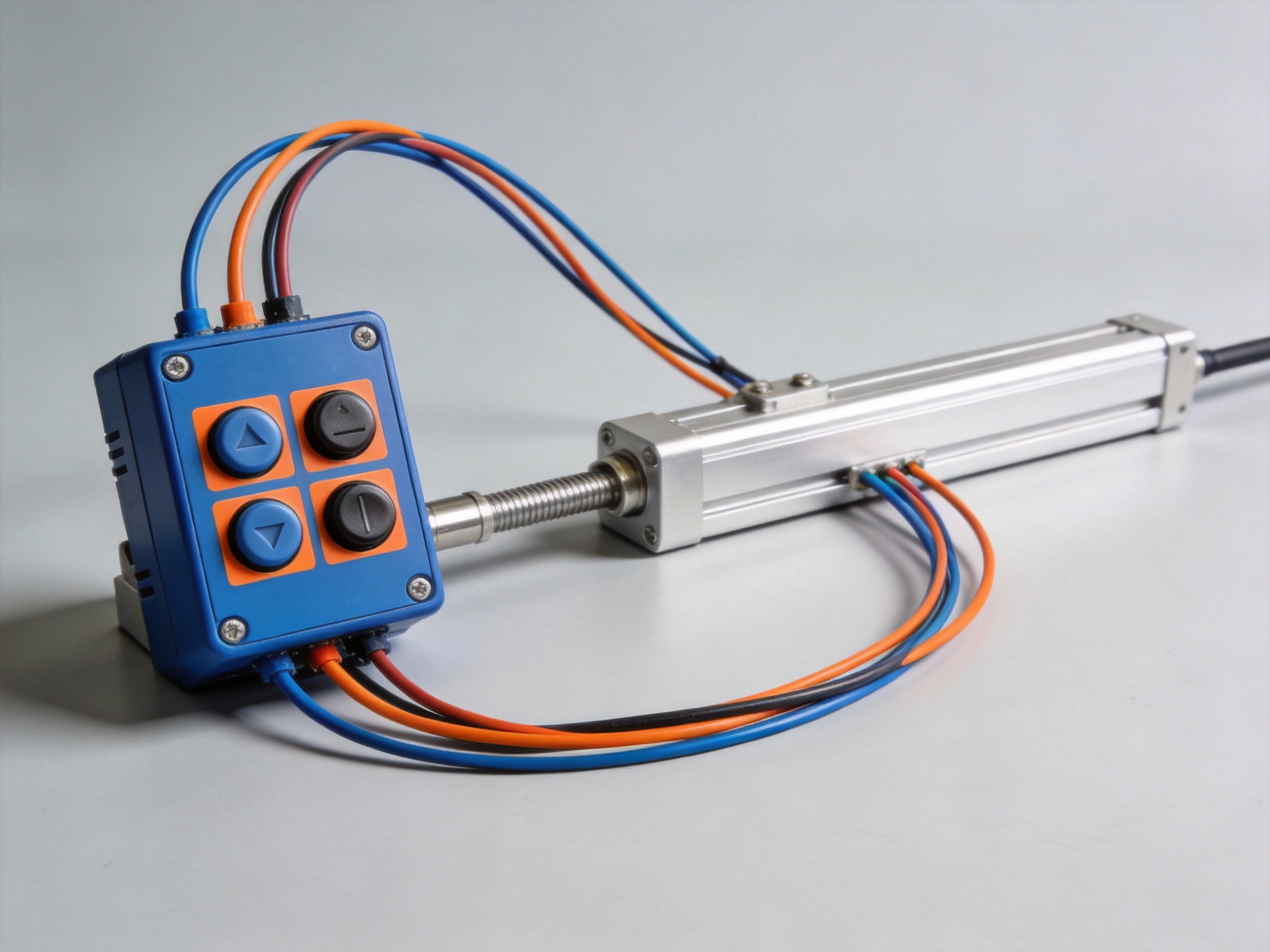
2.2 Standard Wiring Connections
A typical wiring diagram connects power inputs, motor outputs, and control signals. The controller requires a DC power supply input (e.g., 12V or 24V) and two output terminals to the linear actuator motor. The four buttons are internally connected to the logic circuit.
Power Input: Connect to a DC power source matching the actuator's voltage rating.
Motor Output (A/B): Connect to the two wires of the linear actuator's DC motor.
Ground: Ensure a common ground is established between power supply, controller, and system.
Understanding this electrical logic is key to troubleshooting and enables seamless integration into larger automated systems, where these manual controllers can serve as a local override.
Essential Tools and Components for Wiring Your Controller
Properly wiring a 4 Buttons DC Motor Controller requires more than just the controller itself. Field experience shows that having the right tools and components on hand before starting prevents frustration and ensures a safe, reliable connection. MEIMOVE engineers emphasize that preparation is the most critical phase for a successful installation.
1. Essential Hand Tools and Safety Gear
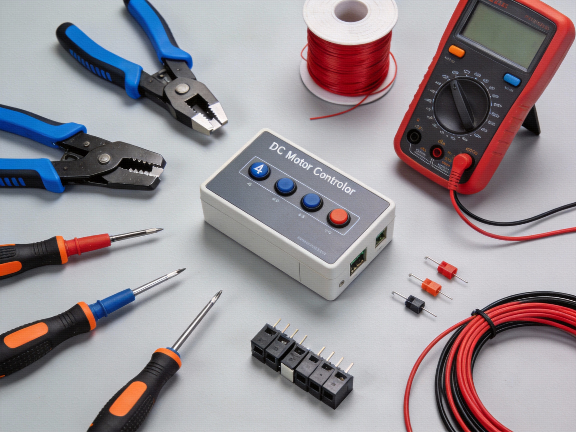
1.1 Core Wiring Tools
A basic actuator wiring kit should include a wire stripper, crimping tool, and a digital multimeter. The wire stripper must handle the common 22-16 AWG gauge used for signal and power lines in most DC motor setups.
In practice, a quality crimping tool ensures secure, gas-tight connections on spade or ring terminals, which are more reliable than simple wire twists for vibration-prone applications.
1.2 Measurement and Safety Equipment
A digital multimeter is non-negotiable for verifying voltage, continuity, and resistance. Before applying power, always check for short circuits between power and ground terminals.
Personal protective equipment (PPE) like safety glasses and insulated gloves should be standard. A common mistake is skipping PPE for "quick" 12V or 24V DC work, but accidental shorts can still cause injury or damage components.
Pro Tip: MEIMOVE's technical team recommends keeping a dedicated "low-voltage toolkit" with color-coded hook-up wire (red for V+, black for GND), assorted ferrules, and a set of precision screwdrivers for terminal blocks.
2. Key Electrical Components and Specifications
2.1 Power Supply and Protection
The DC power supply must match your motor's voltage (e.g., 12V, 24V) and provide sufficient current. A good rule is to select a supply with a continuous current rating at least 25% higher than the motor's stall current to handle startup surges.
Circuit protection is critical. Always install an appropriately rated inline fuse or circuit breaker on the positive lead from the power supply to the controller. This protects against wiring faults and motor overloads.
2.2 Connectors and Wiring
Use the correct connectors for a robust installation. For the motor and power leads, spade or ring terminals secured under screw terminals are preferred. For signal wires to buttons or sensors, Dupont-style connectors are common.
Refer to the table below for recommended component specifications based on a typical 24V DC actuator system:
Component | Recommended Specification | Purpose |
Wire Gauge (Power) | 16 AWG | Handles high current to motor, minimizes voltage drop. |
Wire Gauge (Signal) | 22 AWG | Sufficient for low-current button/sensor circuits. |
In-line Fuse | Slow-blow, 125% of motor FLA | Protects against sustained overloads without nuisance tripping. |
DC Power Supply | 24V, 10A (min.) | Provides stable voltage with overhead for peak demands. |
With your tools organized and components verified, you can proceed confidently to the physical wiring and connection phase, where attention to detail ensures optimal controller performance.
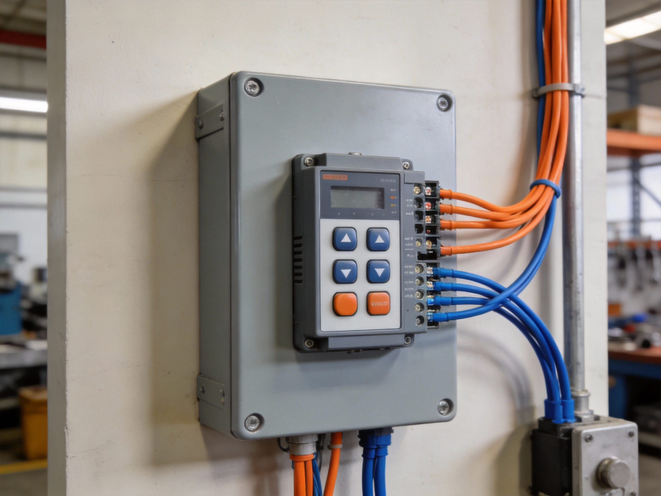
Step-by-Step Guide to Wiring the 4-Button DC Motor Controller
Wiring a 4-button DC motor controller is a straightforward process when you follow a logical sequence. This guide provides a detailed, step-by-step procedure to ensure a safe and functional installation, from power connection to actuator output. MEIMOVE engineers recommend always verifying your specific controller's datasheet before starting, as terminal labels can vary by manufacturer.
1. Preparation and Safety
1.1 Required Tools and Materials
Gather all necessary components before beginning. You will need the 4-button controller, a compatible DC power supply, the DC motor or linear actuator, and appropriate gauge wire. Essential tools include wire strippers, a screwdriver set, and a digital multimeter for verification.
A complete setup kit typically includes:
DC power supply matching controller's voltage input (e.g., 12V or 24V)
16-22 AWG stranded copper wire for low-current signal connections
Wire ferrules or terminals for a secure connection in screw terminals
Digital multimeter to check voltage and continuity
1.2 Initial Safety Precautions
Always disconnect all power sources before handling wires or making connections. Verify the power supply is off using a multimeter. Identify and clearly label all wires according to your system diagram to prevent cross-connection, which can damage the controller or motor.
Pro Tip: For reliable long-term performance, MEIMOVE's technical team suggests using a dedicated circuit breaker or fuse on the power input line, rated for 125-150% of the controller's maximum current draw.
2. Wiring the Power and Control Inputs
2.1 Connecting the DC Power Supply
Locate the power input terminals, commonly labeled V+ (or VCC) and GND (or COM). Connect the positive lead from your DC power supply to the V+ terminal and the negative lead to the GND terminal. Ensure wire strands are fully inserted into the terminal block and the screws are firmly tightened to prevent arcing.
Field experience shows that loose power connections are a primary cause of intermittent operation and controller failure.
2.2 Identifying and Connecting the Control Buttons
The four control buttons correspond to specific motor functions: Up, Down, Stop, and sometimes a preset position. The controller will have terminals for each (e.g., UP, DOWN, COM). Connect one wire from each momentary button to the common (COM) terminal.
Connect the other wire from each button to its respective function terminal. Use your multimeter's continuity setting to verify each button press closes the correct circuit before applying power.
3. Connecting the Motor and Final Verification
3.1 Terminating the Motor or Actuator Wires
Find the motor output terminals, often marked M+ and M-. Connect the positive wire from your DC motor to M+ and the negative wire to M-. For a linear actuator with built-in limit switches, ensure you connect to the actuator's power input wires, not the internal sensor wires.
Heavier gauge wire (e.g., 14-18 AWG) may be required here depending on the motor's current, which can exceed 5 amps for larger actuators.
3.2 Power-Up Sequence and Functional Testing
Double-check all connections against your wiring diagram. Briefly apply power and press the "Up" button. The motor should run in one direction; pressing "Down" should reverse it. The "Stop" button should halt motion immediately.
If the motor does not respond, disconnect power and check for: incorrect power polarity, loose connections, or a tripped fuse. Never hold a button down if the motor is stalled, as this can overheat the controller.
Understanding the Wiring Diagram: A Detailed Breakdown
A clear wiring schematic is the blueprint for a successful installation. This guide breaks down a standard 4 Buttons DC Motor Controller diagram, explaining each connection point to ensure reliable operation and prevent common wiring errors.
1. Power and Ground Connections
1.1 VCC and GND Terminals
The VCC (Voltage Common Collector) and GND (Ground) terminals provide the controller's operating power. Typically, a 5V to 36V DC power supply connects here, with the voltage directly determining the motor's maximum speed.
Incorrect polarity is a primary failure cause. The red wire must connect to VCC and the black wire to GND; reversing them can instantly damage the controller's internal circuitry.
1.2 Motor Output Terminals (M+ and M-)
Terminals labeled M+ and M- connect directly to your DC motor's positive and negative leads. The controller modulates the voltage and polarity across these outputs to control speed and direction.
For motors drawing over 10A, ensure wire gauge is sufficient (e.g., 12 AWG) to prevent voltage drop and overheating. A loose connection here can cause erratic motor behavior.
2. Control Inputs and Signal Flow
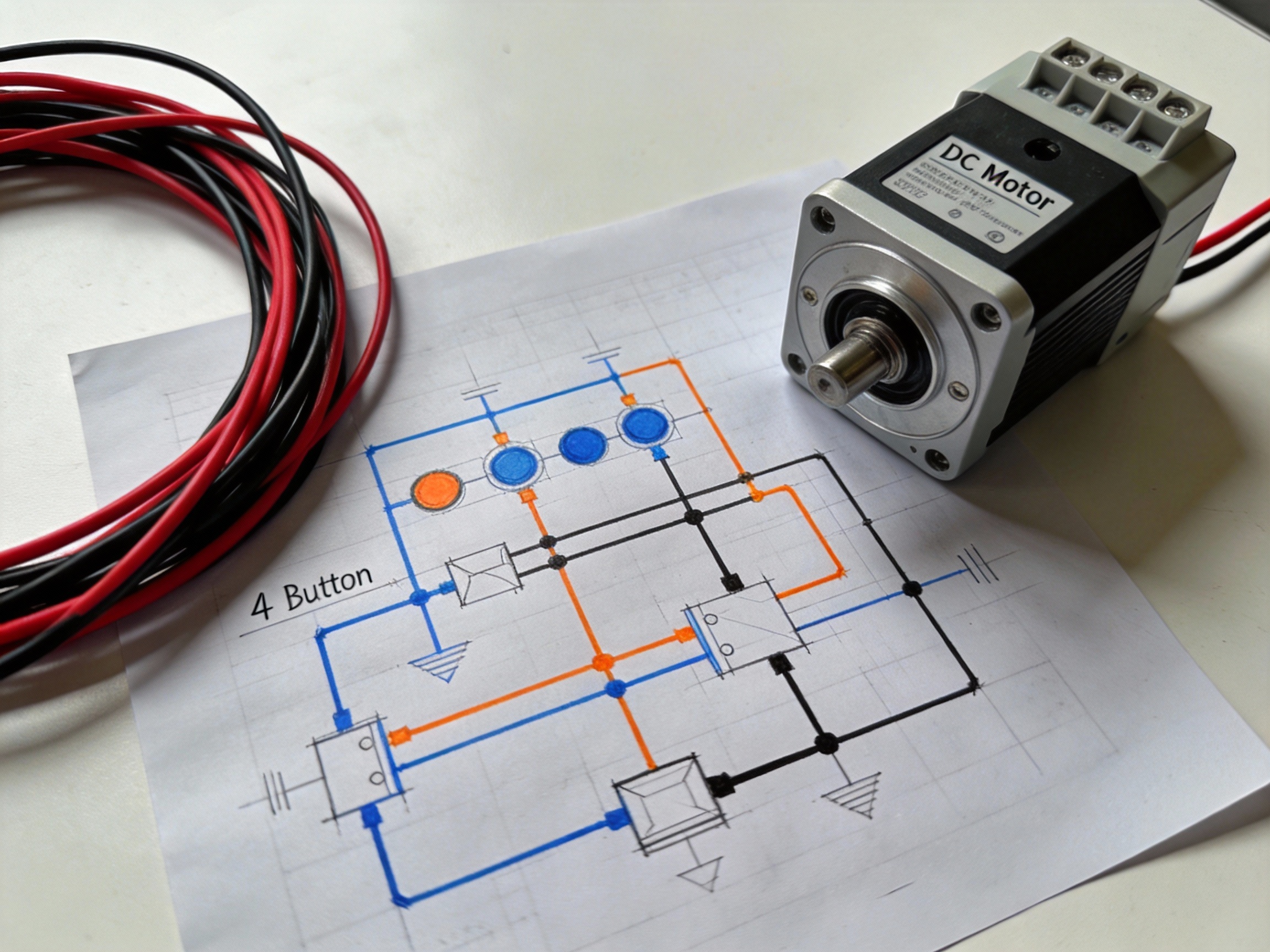
2.1 Button Input Terminals (S1-S4)
Terminals S1 through S4 are the signal inputs for the control buttons. Each button acts as a momentary switch, connecting its terminal to ground (GND) when pressed.
The internal logic is programmed to interpret these ground signals. For example, pressing the button connected to S1 might command "forward," while S2 commands "reverse."
2.2 Wiring the Control Interface
Each button requires two connections: one wire to its designated controller terminal (S1, S2, etc.) and a second wire daisy-chained to the common GND rail. This creates a complete circuit only when the button is pressed.
Use 22-24 AWG stranded wire for flexibility
Implement strain relief on all button connections
Test continuity for each button press before final assembly
Pro Tip: For complex multi-controller setups, MEIMOVE engineers recommend first verifying signal integrity with a multimeter. A common pitfall is shared ground loops causing signal crosstalk between modules.
3. Interpreting the Schematic Legend
3.1 Color-Code and Symbol Guide
A proper legend decodes the diagram's visual language. Red lines typically denote positive power (VCC), black lines are ground (GND), and blue or yellow lines often represent control signal paths.
Symbols like a circle with an "M" indicate the motor, while a rectangle with terminals shows the controller. Understanding these symbols allows you to trace the complete electrical path from power source to motor.
3.2 Terminal Function Reference Table
This table provides a quick reference for each terminal's purpose, a crucial step before connecting any wires.
Terminal Label | Function | Typical Wire Color | Connection To |
VCC | Positive DC Power Input | Red | Power Supply (+) |
GND | Ground / Common Return | Black | Power Supply (-) & Buttons |
M+ / M- | Motor Output Positive/Negative | Varies | DC Motor Leads |
S1, S2, S3, S4 | Control Signal Inputs | Blue, Yellow, Green, White | Momentary Push Buttons |
With each connection point clearly defined, you can proceed confidently to the physical assembly and testing phase.
How Do You Connect a 4-Button Controller to a 12V Linear Actuator?
Connecting a 4-button DC motor controller to a 12V linear actuator is a straightforward process centered on three critical factors: voltage matching, current capacity, and correct polarity. MEIMOVE engineers emphasize that verifying these specifications before connection prevents damage and ensures reliable operation.
1. Core Connection Specifications
1.1 Voltage and Current Matching
The controller and actuator must share the same nominal voltage, typically 12V DC. The controller's current rating must exceed the actuator's maximum draw, which can range from 2A to 10A or more under load. Field experience shows that undersizing the controller is a common cause of failure.
Component | Critical Specification | Checkpoint |
Linear Actuator | Rated Voltage (e.g., 12VDC) | Nameplate or datasheet |
4-Button Controller | Output Voltage & Max Current (e.g., 12VDC, 10A) | Product label or manual |
1.2 Wiring and Polarity
A standard 4-button controller has two main power terminals (often labeled M+ and M-) for the actuator motor wires. The actuator's two wires connect directly here. Reversing these wires will cause the actuator to move in the opposite direction of the button press, which can be hazardous.
Pro Tip: Before finalizing connections, MEIMOVE technicians recommend a brief tap test: momentarily press a button to confirm the actuator extends and retracts as expected, verifying polarity is correct.
2. Step-by-Step Connection Guide
2.1 Preparation and Safety
Always disconnect the power source before making any connections. Gather the necessary tools and verify all component ratings. In practice, having a multimeter to confirm voltage and continuity is invaluable for troubleshooting.
Wire strippers and crimp connectors
Multimeter for verification
12V DC power supply (battery or adapter)
Electrical tape or heat shrink tubing
2.2 Terminal Connection Process
First, connect the power supply's positive and negative leads to the controller's input terminals (e.g., V+ and V-). Next, connect the actuator's two wires to the controller's motor output terminals (e.g., M+ and M-). Secure all connections firmly to prevent arcing or voltage drop.
Finally, restore power. The controller's LED should illuminate, indicating it is ready. Pressing the "Up" and "Down" buttons should now smoothly control the actuator's movement in the correct directions.
For a detailed guide on selecting the right controller, actuator force calculations, and advanced wiring diagrams for multi-actuator setups, continue to our comprehensive resource on linear actuator systems.
Practical Applications for Your Wired Actuator Controller
A 4 Buttons DC Motor Controller is the cornerstone of countless DIY automation projects, transforming simple linear motion into smart, functional systems. This chapter explores practical applications to inspire your next build, from home offices to gardens.
1. Home and Office Automation
1.1 Adjustable Standing Desk
Convert a standard desk into a height-adjustable workstation using a linear actuator and a 4-button controller. This setup typically requires a 12V or 24V DC actuator with a thrust rating over 500 lbs to safely lift a desktop and monitors.
The controller allows precise, incremental adjustments between sitting (28 inches) and standing (42 inches) positions, promoting ergonomics. For stability, MEIMOVE engineers recommend using two synchronized actuators controlled by a single unit.
1.2 Automated Window Blinds or Blackout Curtains
Integrate a small, low-voltage actuator to automate heavy curtains or horizontal blinds. The controller provides simple open, close, and stop functions, which can be triggered manually or connected to a smart home timer.
Key considerations include the actuator's stroke length (must match your window width) and speed. A common setup uses a 12V DC actuator with a 20-inch stroke, moving at approximately 0.5 inches per second for smooth, quiet operation.
Pro Tip: When planning an automated desk, always calculate the total weight (desktop + equipment) and add a 25% safety margin before selecting your actuator's thrust capacity. MEIMOVE's project guides provide detailed calculation worksheets.
2. Outdoor and Mechanical Projects
2.1 Solar Panel Tracker System
Increase solar energy efficiency by building a single-axis tracker that tilts panels to follow the sun. A weatherproof 4-button controller allows manual seasonal adjustment or can be part of an automated light-sensing circuit.
The system requires an actuator with high corrosion resistance and a holding brake to withstand wind loads. A typical residential tracker might use an actuator with a 24-inch stroke and 1500 lb rating to move multiple panels.
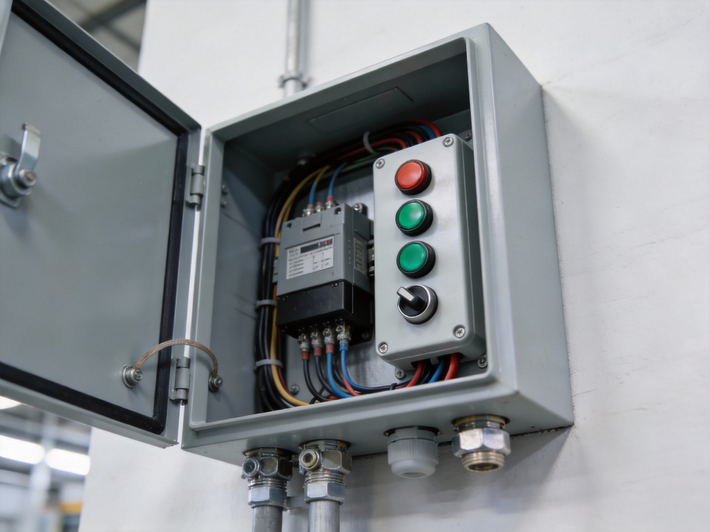
Create a robust entry system for a swing or sliding gate. The wired controller offers reliable, direct operation without wireless signal issues, ideal for remote or metal-heavy installations that can interfere with radio frequencies.
Essential project components include:
A high-thrust (2000+ lb) DC actuator for moving heavy gates
Weatherproof enclosure for the controller and wiring
Limit switches to define fully open and closed positions
Foundation hardware for secure actuator mounting
These applications demonstrate the versatility of a simple wired controller. For detailed wiring diagrams and step-by-step project plans, explore technical forums and maker communities dedicated to DIY automation projects.


Comments