4 Types of DC Motor Ranked by Torque and Performance
- Xie
- Jan 23
- 21 min read
Updated: Jan 26
What is a DC Motor? Understanding the Basics
A DC (Direct Current) motor is an electromechanical device that converts electrical energy from a direct current source into mechanical rotation. This fundamental principle powers countless applications, from industrial machinery to consumer electronics. For engineers and procurement specialists, understanding the core components and operation is the first step in selecting the right motor for a project, a process where MEIMOVE often provides technical consultation.
1. Core Definition and Working Principle
1.1 The Basic Electromechanical Concept
The operation of a DC motor is based on the Lorentz force law: a current-carrying conductor within a magnetic field experiences a mechanical force. In practice, this force creates torque on the motor's rotor, causing it to spin. The direction of rotation is determined by Fleming's Left-Hand Rule for motors, linking current, magnetic field, and motion.
This conversion is continuous due to a critical component called the commutator, which reverses the current direction in the rotor coils as it spins, maintaining unidirectional torque.
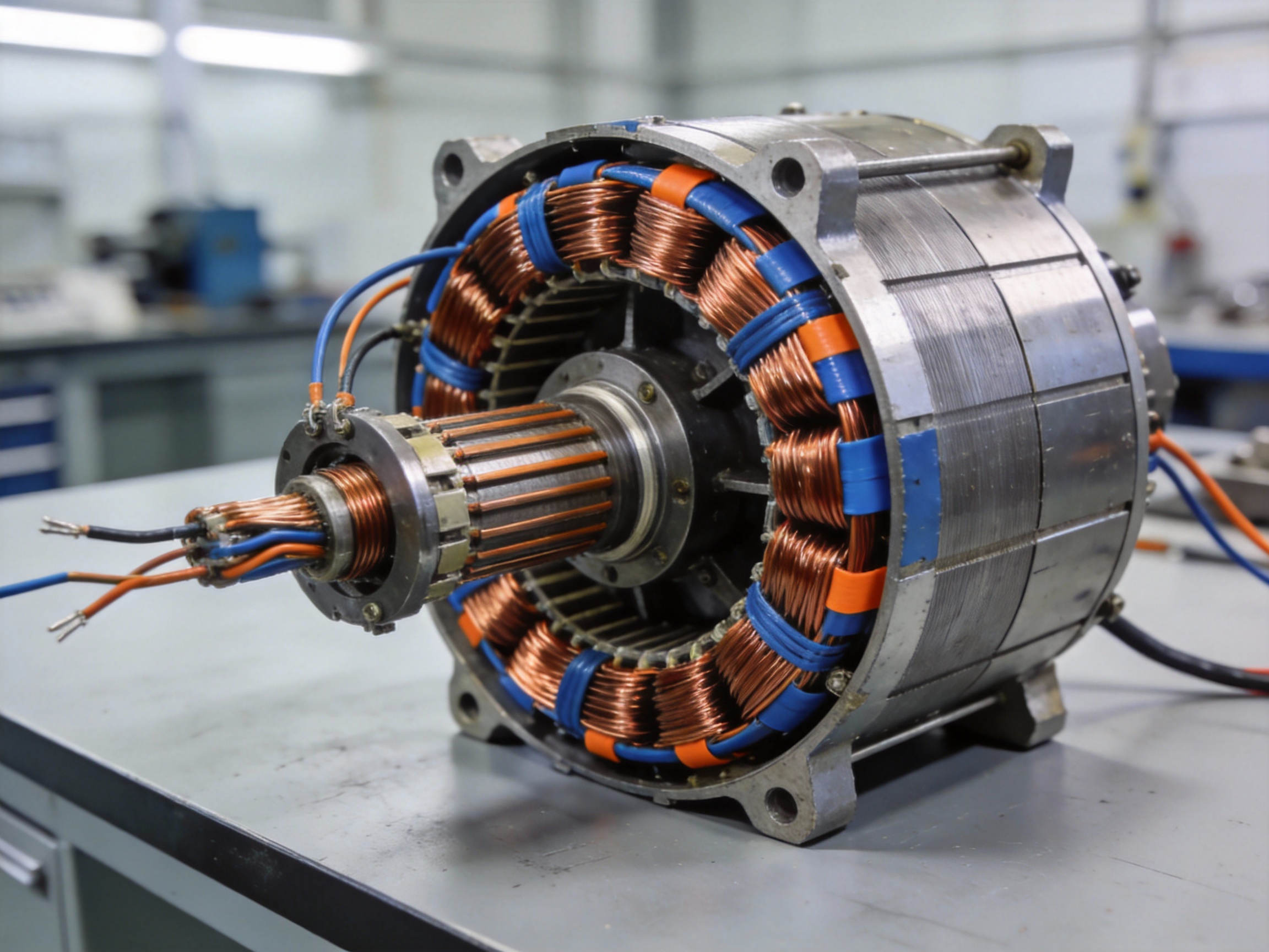
1.2 Key Components and Their Roles
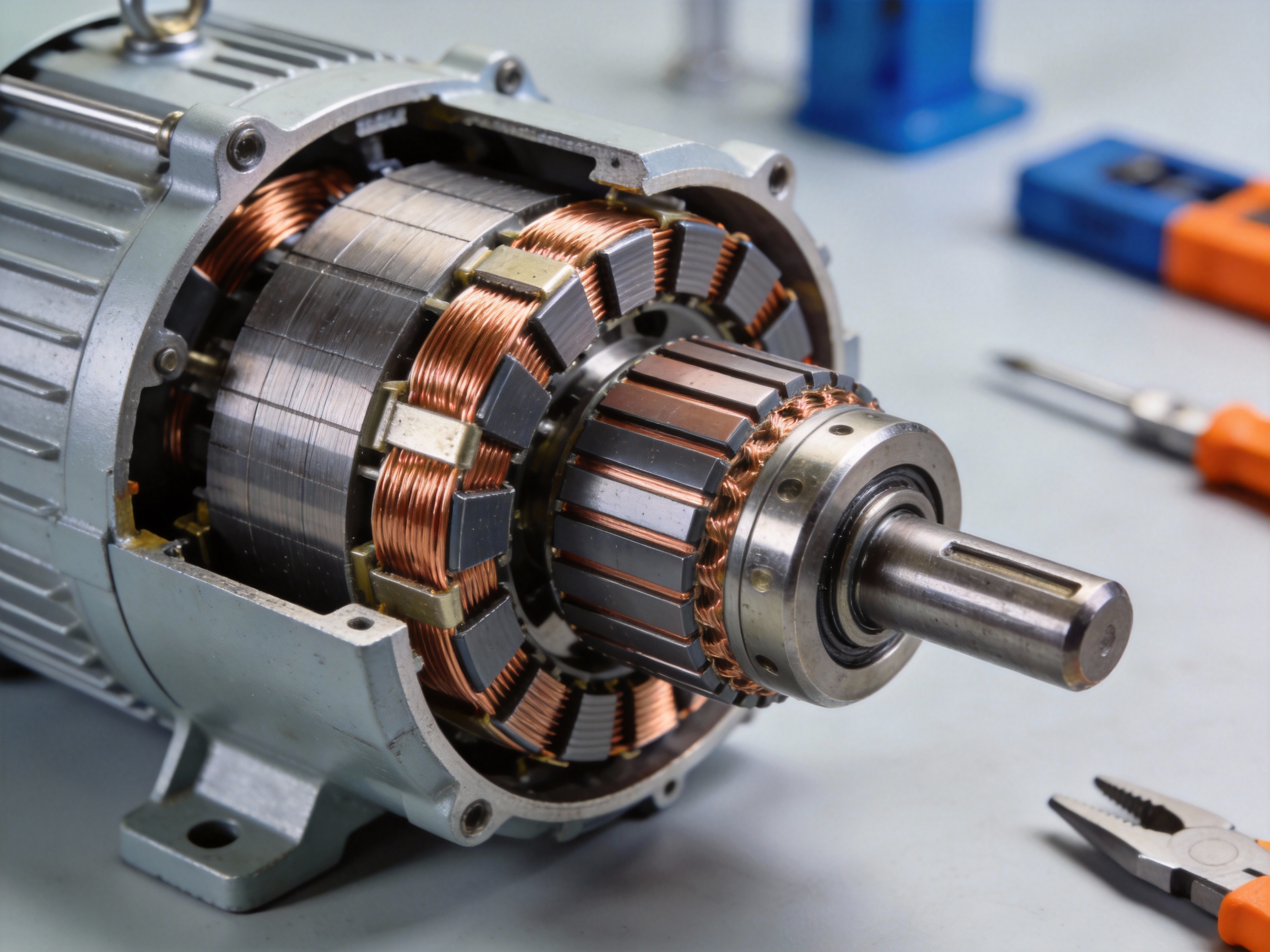
Every DC motor is built around four essential parts that enable its function. The stator provides the stationary magnetic field, typically using permanent magnets or field windings. The rotor (or armature) is the rotating part, containing coils of wire that carry the current.
The commutator, a mechanical rotary switch mounted on the rotor shaft, and the carbon brushes that press against it, work together to periodically reverse the current in the armature coils, ensuring continuous rotation.
Stator: Creates the stationary magnetic field (permanent magnets or electromagnets)
Rotor (Armature): The rotating core with wound coils that carry current
Commutator: Segmented copper cylinder on the shaft that reverses current
Brushes: Typically carbon blocks that conduct current to the spinning commutator
Pro Tip: MEIMOVE engineers note that brush and commutator wear is the primary failure mode in traditional DC motors. For applications requiring high reliability and low maintenance, consider brushless DC (BLDC) motor alternatives from the outset.
2. Fundamental Performance Characteristics
2.1 Torque, Speed, and Voltage Relationships
The performance of a DC motor is defined by key interlinked parameters. The torque produced is directly proportional to the armature current and the strength of the magnetic field. Conversely, the motor's rotational speed is proportional to the applied voltage and inversely proportional to the magnetic flux.
This leads to a fundamental characteristic: a DC motor provides high starting torque, which decreases as speed increases. The no-load speed is typically limited by the supply voltage and internal friction.
2.2 Efficiency and Loss Considerations
Efficiency in a DC motor is reduced by several inherent losses. Copper losses (I²R) occur due to resistance in the windings. Mechanical losses include bearing friction and windage. Core losses (hysteresis and eddy currents) happen in the magnetic iron.
In field experience, a standard brushed DC motor typically operates at 75-85% efficiency under optimal load. Efficiency drops significantly at very low or very high loads relative to the motor's rated capacity.
How to Choose the Right DC Motor for Your Application
Selecting the optimal DC motor requires a systematic evaluation of your application's core mechanical and electrical demands. This guide outlines the critical selection criteria, providing a practical framework to match motor specifications with your project's needs, ensuring performance and reliability. MEIMOVE engineers use a similar methodology to specify motors for custom automation solutions.

1. Define Your Application's Core Requirements
1.1 Analyze Mechanical Load and Torque
Start by calculating the required torque, which is the rotational force needed to move your load. This includes both continuous torque for steady operation and peak torque for startup or overcoming inertia. In practice, a common mistake is underestimating peak torque, leading to motor stalling.
For a conveyor belt, you must account for the weight of the items, friction, and acceleration. Use the formula: Torque (N·m) = Force (N) x Radius (m). Field experience shows adding a 20-25% safety factor to calculated values prevents performance issues.
1.2 Determine Speed and Power Needs
Operating speed (RPM) directly impacts motor choice, as different types have inherent speed ranges. Brushed DC motors, for instance, typically excel below 5,000 RPM. Power (Watts) is the product of torque and speed, defining the motor's overall capability.
Use the power equation: Power (W) = Torque (N·m) x Speed (rad/s). A robotic arm joint might need high torque at low speed (< 100 RPM), while a cooling fan prioritizes high speed with minimal torque. Matching power ensures the motor isn't under or over-sized.
Pro Tip: MEIMOVE's technical team recommends creating a load profile chart. Plot required torque versus speed across the entire duty cycle to visualize if a motor's performance curve can cover all operational points, especially during acceleration.
2. Evaluate Motor Control and Performance Factors
2.1 Assess Speed Control and Efficiency
Consider how precisely you need to control speed. Brushed DC motors offer simple, cost-effective speed control via voltage variation. Brushless DC (BLDC) motors provide superior speed regulation and higher efficiency, often exceeding 85-90%, but require an electronic controller.
Efficiency impacts heat generation and energy costs. For battery-powered applications like mobile robots, choosing a high-efficiency BLDC motor can extend operational runtime by 15-20% compared to a brushed equivalent.
2.2 Consider Physical and Environmental Constraints
The motor's physical size (frame size), mounting type (foot, flange, face), and weight must fit your design envelope. Environmental factors like temperature, humidity, and exposure to dust or chemicals dictate the required ingress protection (IP) rating.
A washdown-duty food processing machine requires a stainless steel housing and an IP rating of at least IP65. For high-ambient-temperature environments, verify the motor's insulation class (e.g., Class F for 155°C) to ensure reliable operation.
3. Application-Based Selection Checklist
Use this checklist to document your application's specifications and narrow down motor types of DC motor options. This systematic approach prevents overlooking key parameters.
Selection Criteria | Your Application's Requirement | Motor Type Considerations |
Continuous Torque | ______ N·m | Brushed: Good for moderate torque. BLDC/Servo: Best for high torque. |
Peak Torque | ______ N·m | Ensure motor can deliver 150-200% of continuous torque briefly. |
Operating Speed Range | ______ to ______ RPM | Brushed: Lower range. BLDC: Wide, high-speed range. |
Control Precision | Basic / Moderate / High | High precision requires BLDC with encoder or a servo motor. |
Duty Cycle | Continuous / Intermittent | Intermittent duty allows for smaller motors if peak specs are met. |
Power Source | Battery / Regulated DC | Battery apps prioritize high efficiency (BLDC). |
Environment | IP Rating: ______ | Harsh environments need sealed (IP65+) or specialized motors. |
By methodically defining torque, speed, power, and environmental needs, you establish a clear specification profile. This profile is essential for effectively comparing the performance characteristics of different DC motor types, which we will detail next.
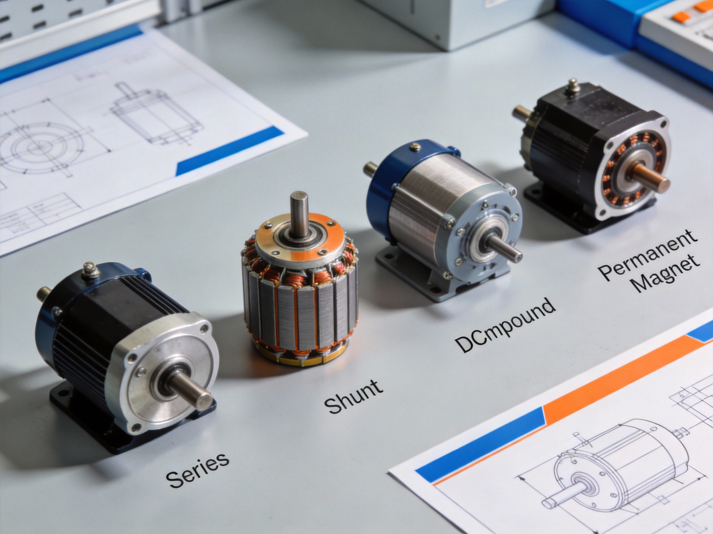
Permanent Magnet DC Motor (PMDC): High Efficiency and Simple Control
Among the various Types of DC Motor, the Permanent Magnet DC (PMDC) motor stands out for its straightforward design and reliable performance. Its defining feature is the use of high-strength permanent magnets to create the stator's magnetic field, eliminating the need for separate field windings and their associated power consumption. This inherent design choice directly translates to the high efficiency and simple control that make PMDC motors a preferred solution for applications from automotive accessories to industrial automation. MEIMOVE engineers frequently specify PMDC motors in projects where space, cost, and control simplicity are critical constraints.
1. Construction and Operating Principle
1.1 Core Components and Diagram
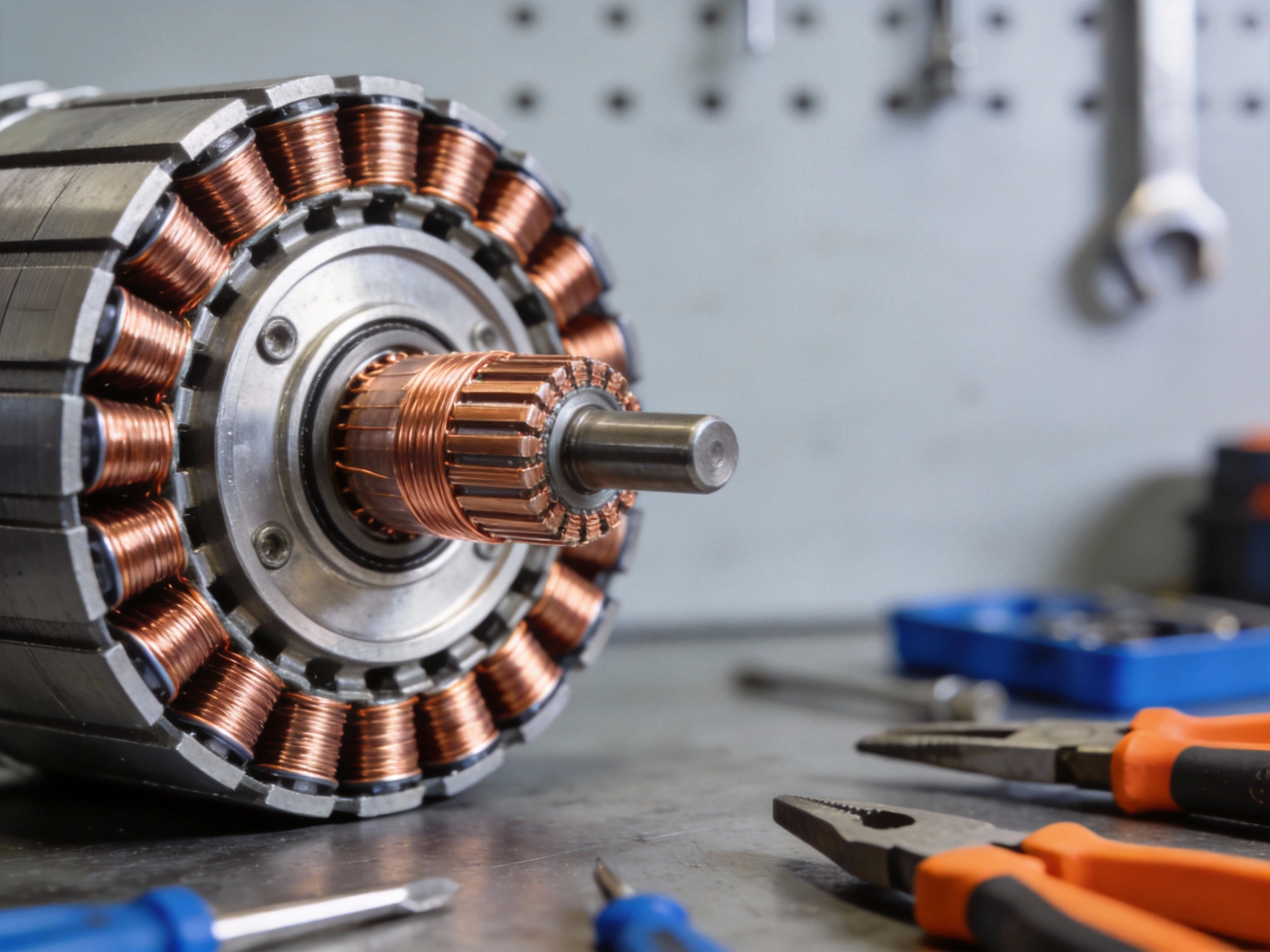
The PMDC motor's construction is elegantly simple. The stator consists of a steel housing with two or more permanent magnets (often made of neodymium or ferrite) fixed to its inner surface, providing a constant magnetic field. The rotor, or armature, is a laminated iron core with windings connected to a commutator.
In practice, applying DC voltage to the brushes causes current to flow through the armature windings, creating an electromagnetic field. The interaction between this field and the fixed stator field produces torque, causing the rotor to turn. The commutator and brushes continuously reverse the current direction in the windings to maintain rotation.
1.2 Inherent Torque-Speed Characteristics
The PMDC motor exhibits a linear, inversely proportional relationship between speed and torque, a key characteristic defined by its construction. As the load torque increases, the motor speed decreases predictably. This linear torque-speed curve simplifies control algorithms significantly.
Field experience shows that at no load, the motor reaches its maximum speed, limited primarily by friction and windage. Under stall conditions (zero speed), it produces its maximum torque, known as stall torque. This predictable behavior makes speed control via simple voltage adjustment highly effective.
Pro Tip: When analyzing a PMDC motor's performance, always reference its datasheet torque-speed curve. MEIMOVE's technical team notes that operating consistently near the stall torque point can cause excessive armature current and overheating, reducing the motor's service life.
2. Performance Advantages and Limitations
2.1 High Efficiency and Key Data
The primary efficiency gain in a PMDC motor comes from eliminating the power loss associated with field windings. Since the magnetic field is supplied by permanent magnets, no electrical energy is consumed to excite the stator. This can lead to efficiencies of 75-85% at rated load, which is notably higher than equivalent shunt-wound DC motors in their typical operating range.
This efficiency advantage is most pronounced in applications with frequent start-stop cycles or variable loads, as there is no lag in building the magnetic field. The immediate availability of full field strength contributes to excellent starting torque, often 2-3 times the rated running torque.
2.2 Pros, Cons, and Application Fit
Choosing a PMDC motor involves weighing its inherent benefits against its limitations for a specific use case. Its simplicity is both a strength and a constraint.
Compact size and lower weight due to simplified stator construction
Excellent linear speed control through armature voltage variation
High starting torque and rapid dynamic response
Risk of permanent magnet demagnetization from excessive heat or armature reaction
Brush and commutator wear requires periodic maintenance
Performance is sensitive to temperature fluctuations
This balance makes PMDC motors ideal for low-to-medium power applications like power windows, windshield wipers, small conveyors, and precision tools, where their efficiency and control simplicity outweigh maintenance considerations. For harsh environments or maintenance-free requirements, brushless alternatives may be more suitable.
Series Wound DC Motor: Maximum Starting Torque Explained
A series wound DC motor is a specific type of DC motor where the field winding is connected in series with the armature winding. This unique configuration is engineered to deliver exceptionally high starting torque, making it the go-to choice for applications requiring heavy-load startups, such as industrial cranes, traction systems, and winches. MEIMOVE engineers frequently specify this motor type for demanding material handling equipment where overcoming initial inertia is critical.
1. How Series Connection Creates High Torque
1.1 The Fundamental Wiring Principle
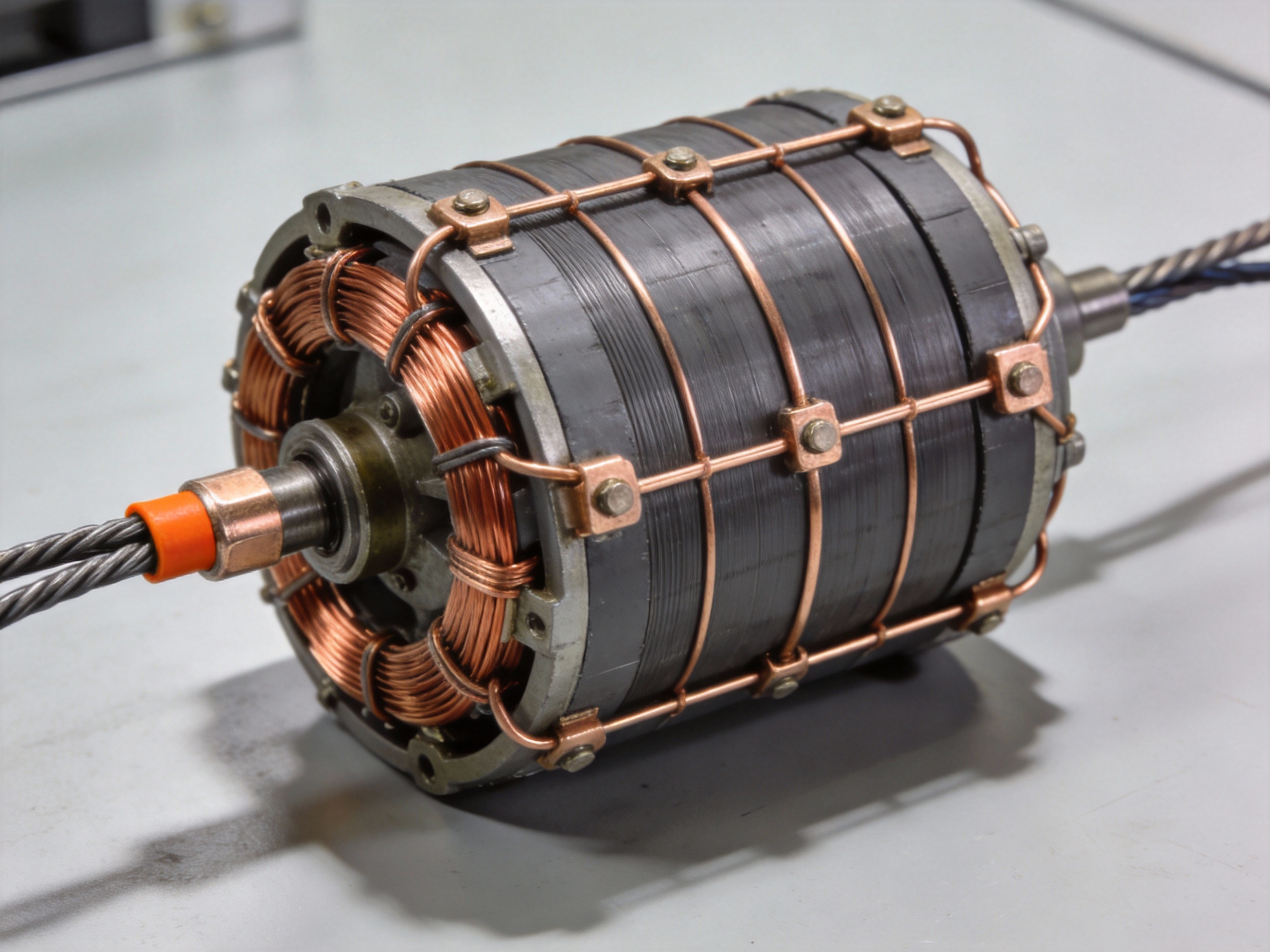
In a series wound motor, the field coil and armature are connected end-to-end, forming a single current path. This means the same current flows through both the field and the armature. The field winding is constructed with relatively few turns of thick wire, presenting low resistance to allow high current flow.
This direct series connection is the key to its torque characteristic, as the magnetic field strength is directly proportional to the armature current.
1.2 The Torque-Current Relationship
The motor's torque (T) is proportional to the product of the armature current (I<sub>a</sub>) and the magnetic flux (Φ). Since flux in a series motor is also directly proportional to I<sub>a</sub> (before magnetic saturation), torque becomes proportional to I<sub>a</sub><sup>2</sup>. This quadratic relationship means a small increase in starting current produces a very large increase in starting torque.
For example, doubling the starting current can theoretically quadruple the starting torque, enabling the motor to break away heavy static loads.
2. Performance Characteristics and Comparison
2.1 Starting Torque Comparison Chart
The table below illustrates the typical starting torque capability of a series wound DC motor compared to other common DC motor types, assuming the same rated voltage and current.
DC Motor Type | Field Winding Connection | Relative Starting Torque | Ideal Application |
Series Wound | In series with armature | Very High | Heavy-load starting (Cranes, Hoists) |
Shunt Wound | In parallel with armature | Medium | Constant speed (Conveyors, Fans) |
Compound Wound | Combination of series & shunt | High | Variable load (Presses, Elevators) |
Permanent Magnet | N/A (Permanent magnets) | Medium-High | Compact drives (Actuators, Robotics) |
2.2 Speed-Torque Behavior
A series motor exhibits a sharply drooping speed-torque curve. Speed is low at high torque (startup) and increases rapidly as the load torque decreases. Under very light loads, speed can become dangerously high.
Key operational parameters include a typical starting torque that can be 300-500% of the full-load rated torque, with the speed varying widely from near-zero at stall to a high no-load value.
Pro Tip:MEIMOVE's technical team emphasizes that a series wound DC motor must never be operated without a mechanical load connected to the shaft. The lack of load torque can cause the motor to accelerate uncontrollably ("run away"), leading to catastrophic mechanical failure.
3. Critical Safety and Application Considerations
3.1 The No-Load Operation Hazard
The most critical safety warning for series motors concerns no-load operation. With minimal load, the motor draws little current, producing weak field flux. Since the counter-EMF is also small, the armature accelerates rapidly in a positive feedback loop until it destroys itself.
Essential safety measures include:
Always coupling the motor to a load before energizing
Using positive mechanical load locks or brakes
Implementing electronic overspeed protection circuits
3.2 Ideal and Unsuitable Applications
Series motors excel in applications requiring high intermittent torque and where direct coupling to the load is guaranteed. They are ideal for traction drives, where the vehicle's weight provides a constant load, and for high-inertia startup scenarios.
They are unsuitable for any application where the load could be disconnected, such as belt-driven systems where the belt might break, or for applications requiring constant speed under varying loads.
This makes the series wound DC motor a powerful but specialized tool within the broader landscape of DC motor types, selected specifically for its unmatched starting force.
Shunt Wound DC Motor: Constant Speed Under Varying Load
Among the main types of DC motor, the shunt wound configuration is engineered for speed stability. Its defining feature is the parallel connection of the field and armature windings to the power supply, which creates a unique load-speed characteristic. This makes it a preferred choice for applications demanding consistent rotational speed, such as machine tools and conveyor systems. MEIMOVE engineers often specify shunt motors for precision industrial drives where speed regulation is critical.
1. Circuit Design and Operating Principle
1.1 Parallel Winding Configuration
The shunt motor's key characteristic is its parallel circuit design. The field winding, made of many turns of fine wire, is connected in parallel (or shunt) with the armature winding across the DC supply. This design maintains a nearly constant field current and thus a steady magnetic flux, independent of the armature current drawn by the load.
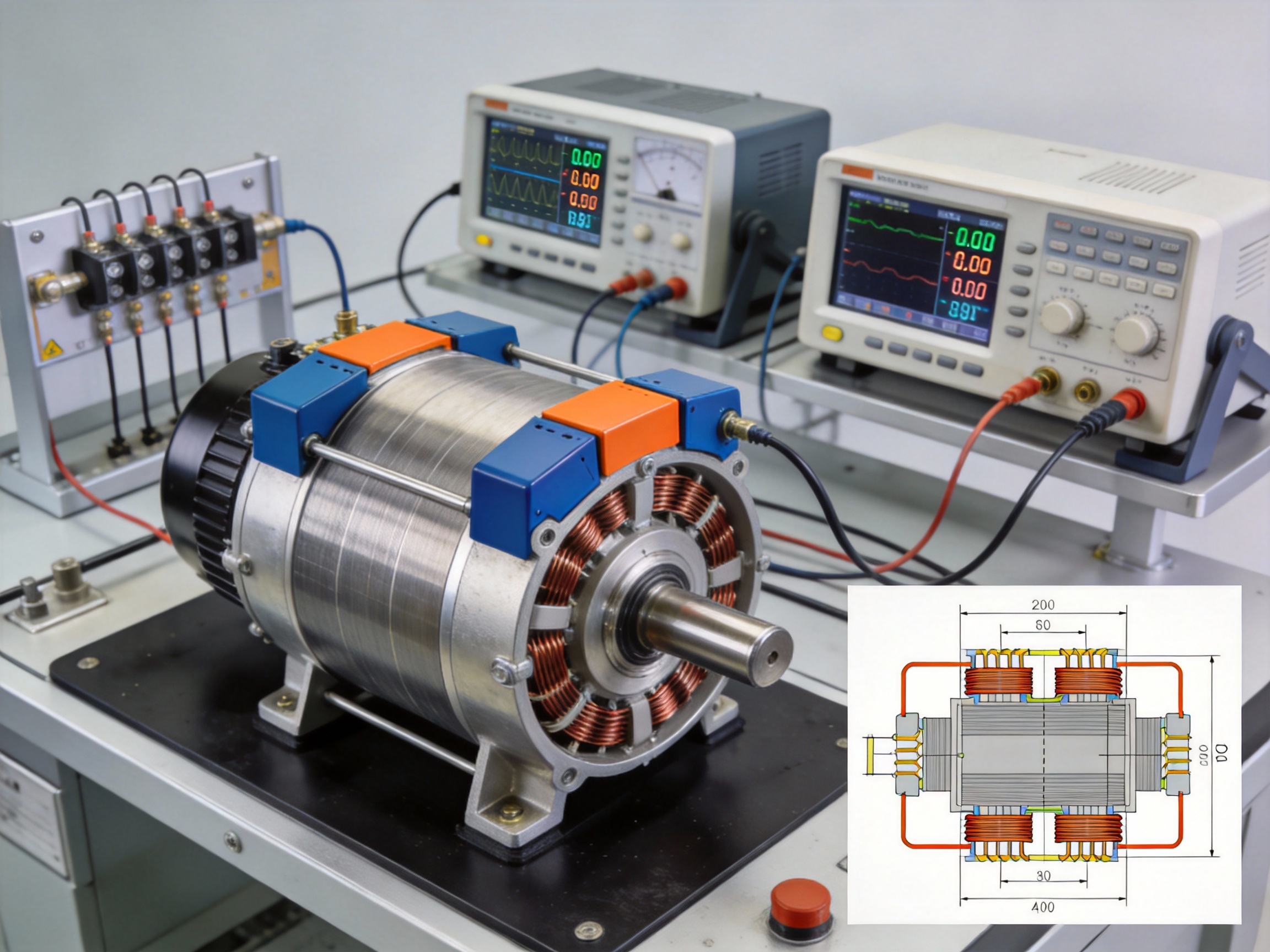
In practice, this means the field strength does not weaken significantly as motor load increases, unlike in a series motor. The circuit schematic clearly shows the parallel paths from the supply terminals to the field and armature, often including a field rheostat for fine speed adjustment.
1.2 The Speed Regulation Mechanism
Speed regulation, defined as (No-load Speed - Full-load Speed) / Full-load Speed, is exceptionally good for shunt motors, typically ranging from 5% to 15%. This performance stems from two counteracting effects: armature reaction and the IR drop in the armature circuit.
As load increases, the armature current rises, causing a slight increase in armature reaction (which tends to weaken flux) and a larger voltage drop across the armature resistance. The net effect is a small, predictable decrease in speed, as illustrated in a nearly flat load vs. speed graph.
2. Performance Characteristics and Applications
2.1 Load-Speed and Torque Behavior
The shunt motor provides a relatively constant speed from no-load to full-load, but its starting torque is only moderate—typically 1.25 to 1.75 times the full-load torque. This is because starting torque is proportional to the armature current, which is limited at start-up by the back EMF being zero.
Therefore, it is not ideal for high-inertia starts. Its torque increases linearly with armature current, making it predictable and controllable for constant-speed applications like lathes, blowers, and centrifugal pumps.
2.2 Industrial Application Case Study
A classic industrial application is in a machine shop's lathe. The motor drives the spindle, which must maintain a constant cutting speed regardless of the varying resistance as the tool engages the workpiece. A shunt motor's flat speed-torque curve ensures consistent surface finish and dimensional accuracy.
Other common applications include:
Conveyor systems requiring steady linear speed
Printing press rollers for consistent feed rates
Centrifugal pumps and fans where output is speed-dependent
Pro Tip: For optimal long-term performance in precision applications, MEIMOVE specialists recommend implementing regular maintenance checks on the commutator and brushes, and ensuring the field rheostat contacts are clean to prevent erratic speed control.
3. Advantages, Limitations, and Comparison
3.1 Key Benefits and Drawbacks
The primary advantage is excellent speed regulation, making it ideal for process control. It is also easily reversible by switching the field or armature leads and allows for smooth speed control via a field rheostat.
The main limitation is its relatively low starting torque. A significant drawback is that if the field circuit opens while running, the motor can "run away" to destructively high speeds as the flux collapses to residual levels, a critical safety consideration.
3.2 Comparison with Other DC Motor Types
Understanding where the shunt motor fits requires comparing its core traits against other main types. The table below highlights key operational differences.
Characteristic | Shunt Motor | Series Motor | Compound Motor |
Speed Regulation | Excellent (5-15%) | Poor (Very High Variation) | Good to Variable |
Starting Torque | Moderate | Very High | High |
Ideal For | Constant-speed drives | High-traction starts | Applications needing both |
This makes the shunt motor the specialist for speed-sensitive applications, whereas series motors excel where high starting torque is paramount.
Compound Wound DC Motor: Combining Series and Shunt Advantages
A compound wound DC motor is engineered to deliver the high starting torque of a series motor and the stable speed regulation of a shunt motor. This hybrid design, which integrates both series and shunt field windings on the same pole, offers a versatile solution for applications requiring a balanced performance profile. MEIMOVE engineers often specify compound motors for industrial drives where load conditions are variable but precise control is still needed.
1. Core Design and Operating Principle
1.1 Field Winding Configuration
The defining feature is its dual-field excitation system. A shunt field winding, with many turns of fine wire, is connected in parallel with the armature, while a series field winding, with fewer turns of thick wire, is connected in series. According to standard motor design principles, the shunt field provides a relatively constant magnetic flux, while the series field flux varies directly with the armature current.
1.2 Cumulative vs. Differential Compounding
Compound motors are classified by how the magnetic fields interact. In a cumulative compound motor, the series field flux aids the shunt field flux, enhancing starting torque by 15-25% over a shunt motor. Conversely, in a differential compound motor, the series field opposes the shunt field, resulting in a nearly constant speed or even a slight speed increase with load, though it has poor starting torque and is rarely used.
2. Performance Comparison and Applications
2.1 Key Performance Characteristics
The compound motor's performance sits between its parent types. It offers starting torque roughly 2.5 to 4 times the full-load torque, significantly better than a shunt motor but less than a pure series motor. Its speed regulation—the change in speed from no-load to full-load—typically ranges from 10% to 30%, providing a stable yet adaptable operation.
Common industrial applications include:
Elevators and hoists requiring strong starting force
Heavy-duty machine tools like planers and punches
Rolling mill drives with sudden load changes
Presses and shears where load varies cyclically
2.2 Compound vs. Series vs. Shunt Motors
The table below summarizes the key operational differences, which are critical for proper motor selection.
Parameter | Series Motor | Shunt Motor | Compound Motor |
Starting Torque | Very High | Moderate | High |
Speed Regulation | Very Poor (Varies widely with load) | Excellent (Nearly constant) | Good/Moderate |
No-Load Condition | Dangerous (Runs away) | Safe | Safe (Cumulative) |
Ideal Application | Traction, cranes | Constant speed drives | Variable load drives |
Pro Tip: For applications with frequent starts under heavy load, MEIMOVE recommends a cumulative compound motor with about a 15-20% series field contribution. This configuration reliably prevents the "runaway" risk of a pure series motor while maintaining robust torque.
3. Selection and Operational Considerations
3.1 Determining the Compounding Level
The degree of compounding is defined by the percentage of total mmf (magnetomotive force) supplied by the series winding. Light compounding (under 10%) behaves almost like a shunt motor, while heavy compounding (over 30%) approaches series motor characteristics. Field experience shows that most industrial applications perform optimally with a 15-25% series field contribution.
3.2 Connection and Reversal
Proper connection of the interpoles and compensating windings, when present, is crucial. To reverse the rotation of a cumulative compound motor, you must reverse the current in <em>both</em> the armature and the series field winding simultaneously, or reverse only the shunt field. Incorrect reversal can convert a cumulative motor into a differential one, causing unstable operation.
This balanced design makes the compound wound DC motor a cornerstone for robust, variable-load industrial systems, seamlessly bridging the gap between pure torque and pure speed stability.
DC Motor Torque and Performance Comparison Chart
Selecting the right type of DC motor requires a clear understanding of how torque, speed, and efficiency trade-offs impact your application. This definitive comparison chart synthesizes key performance data to guide your decision. For projects demanding precise torque control, MEIMOVE engineers often start with this analysis to match motor characteristics to load requirements.
1. Key Performance Indicators Defined
1.1 Torque Characteristics
Starting torque is the maximum torque a motor produces at zero speed, critical for overcoming initial inertia. Shunt motors typically offer moderate starting torque around 150-200% of rated torque, while series motors can exceed 500%.
Speed-torque curve shape defines controllability; a flat curve indicates good speed regulation under variable load.
1.2 Efficiency and Control Factors
Efficiency varies significantly with load. Compound motors often achieve peak efficiencies of 85-90% near 75-100% of rated load. Permanent Magnet (PMDC) motors are highly efficient at rated speed but lack field control.
Speed control range refers to the achievable speed variation from base speed, heavily dependent on the excitation method.
Pro Tip: MEIMOVE's technical team recommends prioritizing starting torque and speed control needs first. A high-inertia conveyor start-up favors a series motor, while a constant-speed pump is better served by a shunt or PMDC type.
2. DC Motor Performance Comparison Table
The table below ranks the four primary DC motor types across critical operational parameters for a standard industrial voltage range (e.g., 12-240 VDC).
Parameter | Series Wound | Shunt Wound | Compound Wound | Permanent Magnet (PMDC) |
Starting Torque | Very High | Medium | High | Medium-High |
Speed Regulation | Poor (Varies greatly with load) | Excellent (Constant ~5% drop) | Good (Better than series) | Good (Fixed field) |
Speed Control Range | Wide (via voltage) | Wide (via armature/field) | Moderate-Wide | Limited (armature only) |
Efficiency at Rated Load | 80-85% | 85-90% | 85-90% | 90-95% |
Relative Cost & Complexity | Low Cost, Simple | Moderate Cost | Higher Cost, Complex | Low-Moderate Cost, Simple |
Ideal Application Example | Cranes, Hoists, Traction | Machine Tools, Conveyors | Presses, Shears, Elevators | Actuators, Robotics, Fans |
3. Ranking Summary and Selection Guide
3.1 Torque Demands Ranking
For pure high-torque needs, the ranking is clear: Series (highest) > Compound > PMDC ≈ Shunt. Field experience shows series motors excel in applications like winches where load is directly coupled to startup.
However, uncontrolled high speed at light load (a series motor trait) can be dangerous, requiring a mechanical load or governor.
3.2 Application-Based Selection
Match the motor type to the primary driver of your application. Use this quick-reference list to narrow choices:
High Starting Torque: Series or Compound wound
Constant Speed: Shunt wound or PMDC
Wide Speed Control: Shunt wound (best control)
Cost-Effective Simplicity: PMDC or Series wound
This performance synthesis highlights that no single motor type is superior; the optimal choice is a function of your specific torque, speed, and control requirements.
Which DC Motor Has the Highest Starting Torque?
The DC series-wound motor delivers the highest starting torque among all DC motor types. This is a direct consequence of its unique electrical configuration, where the field winding is connected in series with the armature. For engineers at MEIMOVE specifying motors for high-inertia startup applications, understanding this torque characteristic is fundamental.
1. The Electromechanical Reason
1.1 The Series-Wound Configuration
In a series-wound DC motor, the field winding and armature winding are connected in a single loop, carrying the same current. At startup (stall condition), this current is at its maximum, producing a correspondingly powerful magnetic field. This design directly links torque production to the square of the armature current.
1.2 The Torque-Current Relationship
The fundamental torque formula for DC motors is T = kΦI<sub>a</sub>, where k is a constant, Φ is the magnetic flux, and I<sub>a</sub> is armature current. In a series motor, flux Φ is directly proportional to I<sub>a</sub> (since they are the same current), making the torque proportional to I<sub>a</sub><sup>2</sup>. This quadratic relationship explains the exceptionally high starting torque.
2. Performance and Application Context
2.1 Torque-Speed Characteristic
Series motors exhibit a steep inverse relationship between torque and speed. While providing high starting torque, their speed can increase dramatically as the load decreases. This characteristic defines their primary application domain in systems requiring massive initial force.
2.2 Typical High-Torque Applications
Series-wound DC motors are the traditional choice for applications demanding breakaway force. Common uses include:
Electric traction systems for trains and trolleys
Automotive starter motors and winches
High-torque industrial hoists and cranes
Heavy-duty material handling equipment
Pro Tip: While series motors offer unmatched starting torque, MEIMOVE engineers emphasize the critical need for a permanent mechanical load or a failsafe controller. Running a series-wound motor unloaded can lead to a dangerous "runaway" condition where speed increases uncontrollably.
3. Comparison with Other DC Motor Types
3.1 Starting Torque Ranking
Field experience shows a clear hierarchy in starting torque capability. The series-wound motor significantly outperforms other configurations due to its current-squared torque relationship, making it the definitive answer to the question of highest starting torque.
DC Motor Type | Field Winding Connection | Relative Starting Torque | Key Characteristic |
Series-Wound | In series with armature | Highest (∝ I<sub>a</sub><sup>2</sup>) | High starting torque, variable speed |
Compound-Wound | Combination of series & shunt | High | Good starting torque, more stable speed |
Shunt-Wound | In parallel with armature | Moderate | Constant speed, moderate starting torque |
Permanent Magnet | Permanent magnets | Moderate to High | Simple, efficient, constant flux |
Selecting the right DC motor type hinges on the specific torque-speed profile required. The series-wound motor's dominance in starting torque makes it indispensable for overcoming high static friction, a critical factor in many industrial drive systems.
Common DC Motor Applications in Industry and Robotics
Selecting the right Types of DC Motor is critical for optimizing performance in demanding applications. In practice, the choice hinges on matching the motor's inherent characteristics—like torque-speed profile, control complexity, and durability—to the specific demands of industrial machinery and robotic systems. MEIMOVE engineers often begin application analysis by evaluating these core operational requirements.
1. Industrial Automation and Material Handling
1.1 Conveyor Systems and Precision Indexing
Brushed DC motors are prevalent in variable-speed conveyor belts due to their simple speed control via voltage adjustment. They provide sufficient torque at low speeds for starting under load. For high-precision indexing or positioning, such as in packaging machinery, brushless DC (BLDC) or servo motors are preferred for their accurate speed holding and rapid dynamic response.
Field experience shows that BLDC motors, with their electronic commutation, offer longer life (>10,000 hours) in 24/7 duty cycles by eliminating brush wear, a common failure point in dusty industrial environments.
1.2 Pump and Fan Drives
Centrifugal pumps and fans represent a classic application for shunt-wound or permanent magnet DC motors. Their ability to provide constant speed under varying load is key. The load torque in these applications increases with the square of the speed, making the motor's natural characteristic a good fit.
For energy efficiency, modern installations increasingly use BLDC motors with variable frequency drives (VFDs). This setup can reduce energy consumption by 20-30% compared to fixed-speed AC alternatives by matching motor speed exactly to demand.
Pro Tip: For harsh industrial environments with conductive dust or moisture, MEIMOVE recommends specifying motors with high IP (Ingress Protection) ratings, such as IP65, to prevent premature failure of internal components.
2. Robotics and Precision Motion Control
2.1 Robotic Joint Actuation and Articulation
Robotic arms and grippers rely heavily on precise torque and position control. Coreless DC motors and BLDC servo motors dominate here. Coreless motors offer very low inertia for fast acceleration/deceleration in lightweight joints, while BLDC servo motors provide high torque density and exact positional feedback via encoders.
In collaborative robots (cobots), torque-controlled BLDC motors are essential for safe human interaction, allowing the robot to sense and react to external forces immediately.
2.2 Mobile Robotics and AGVs
Autonomous Guided Vehicles (AGVs) and mobile platforms typically use geared DC or BLDC motors for wheel drive. Key selection criteria include high starting torque, efficiency across a wide speed range, and reliability. The choice often involves a trade-off:
Brushed DC with Gearbox: Cost-effective solution for moderate-duty cycles.
BLDC with Integrated Controller: Higher efficiency, longer life, and precise speed regulation for complex navigation.
Dual-Motor Differential Drive: Enables skid-steer turning, common in warehouse robots.
3. Case Study Briefs and Selection Matrix
3.1 Application-Based Motor Selection
Linking motor type to task ensures optimal performance and longevity. The table below summarizes typical pairings based on core requirements.
Application | Primary Motor Type | Key Performance Reason |
Factory Conveyor (Variable Speed) | Brushed DC | Simple, cost-effective speed control |
CNC Tool Changer | BLDC Servo | High positional accuracy & rapid movement |
AGV Drive Wheel | Geared BLDC | High efficiency & torque for battery life |
Laboratory Automation | Coreless DC | Low vibration & smooth low-speed operation |
3.2 Industry-Specific Recommendations
For heavy industries like steel or mining, where shock loads are common, series-wound DC motors provide very high starting torque. In cleanroom or food-grade robotics, sealed BLDC motors prevent contamination. Always cross-reference the motor's duty cycle (e.g., S1 continuous, S3 intermittent) with the application's operational profile to avoid thermal overload.
Understanding these common DC motor applications provides a foundation for specifying the right drive, which directly influences system efficiency, reliability, and total cost of ownership. This leads to the critical next step: understanding the control systems that bring these motors to life.
Key Advantages and Disadvantages of Each DC Motor Type
Choosing the right DC motor requires a clear understanding of the inherent trade-offs between each type. This final assessment provides a balanced comparison of DC motor pros and cons to guide your selection. MEIMOVE engineers often start this process by mapping motor characteristics against specific application demands.
1. Comparative Performance Analysis
1.1 Brushed vs. Brushless DC Motors
The primary trade-off centers on maintenance and control complexity. Brushed DC motors offer simple, low-cost speed control but require periodic brush replacement, typically every 1,000 to 3,000 hours of operation. Brushless DC (BLDC) motors eliminate this maintenance but require a more complex and costly electronic controller.
In practice, brushed motors excel in cost-sensitive, intermittent-duty applications, while BLDC motors dominate where long life, high efficiency, and precise control are critical.
1.2 Shunt, Series, and Compound Wound Motors
These wound-field motors differ in how the field coil connects to the armature, drastically altering performance. Shunt motors provide excellent speed regulation (±5-10% from no-load to full-load) but have moderate starting torque. Series motors deliver very high starting torque but suffer from dangerous overspeed at light loads.
Compound motors blend both characteristics, offering strong starting torque and reasonable speed control, making them a traditional choice for industrial loads like presses and conveyors.
Pro Tip: For applications with widely varying loads, MEIMOVE recommends analyzing the torque-speed curve of each motor type. A compound-wound motor often provides the best compromise, preventing the "runaway" risk of a series motor under light load.
2. Decision-Making Framework
2.1 Key Selection Criteria
A structured evaluation prevents over-engineering or under-specification. Focus on these four non-negotiable parameters first: required starting torque, necessary speed range, available power supply (voltage/current), and duty cycle (continuous vs. intermittent).
Field experience shows that mismatching the motor to the duty cycle is a common mistake, leading to premature failure in brushed motors or unnecessary expense for BLDC systems.
2.2 Cost-Benefit Analysis Notes
The total cost of ownership extends far beyond the initial purchase price. Consider brush replacement costs, controller expenses, and energy consumption over the motor's lifespan. While a brushed motor may cost 50% less upfront, a BLDC motor's 15-30% higher efficiency can justify the investment in high-usage scenarios.
Use the following checklist to weigh the trade-offs for your project:
Is maintenance access difficult or costly? (Favors BLDC)
Does the application demand precise speed control? (Favors BLDC or Shunt)
Is very high starting torque required? (Favors Series or Compound)
Is the budget highly constrained for initial capital? (Favors Brushed)
3. Summary of Trade-Offs
The table below provides a side-by-side comparison to summarize the key advantages and disadvantages, serving as a quick-reference guide for final selection.
Motor Type | Key Advantages | Key Disadvantages |
Brushed DC | Simple, inexpensive control; High starting torque; Low initial cost. | Brush maintenance required; Electromagnetic interference (EMI); Lower efficiency. |
Brushless DC (BLDC) | Long lifespan, no brush wear; High efficiency; Excellent speed control; Low EMI. | Requires electronic speed controller; Higher initial cost; Control complexity. |
Shunt Wound | Excellent speed regulation; Parallel field allows independent control. | Moderate starting torque; Speed drops with increased load. |
Series Wound | Very high starting torque; Simple construction. | Poor speed regulation; "Runaway" risk at no-load. |
Compound Wound | Good starting torque; Better speed regulation than series. | More complex construction; Higher cost than shunt or series. |
Ultimately, the optimal choice balances technical requirements with operational and economic constraints. This systematic comparison equips you to move from general types of DC motor to the specific model that delivers reliable performance for your system's needs.


Comments